#

Monday, September 28, 2015

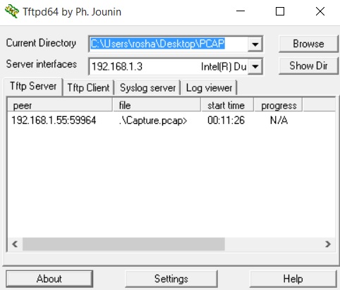
I am using 3 routers with Cisco IOS 15.0 code for this demo. Note that IOS XE routers have a different approach than this. Also I use my laptop as TFTP Server which I use to export and view captured packets.

TFTP software used is TFTPD64 which is configured as the server interface to be the IP address of my laptop's network card.

Captured files will be exported into the folder named PCAP on the desktop.

Setup is simple as shown in the diagram below.
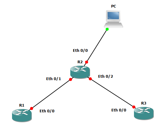


IP address are;

R1 e0/0 : 1.1.1.1

R2 e0/0 : 192.168.1.55
e0/1: 1.1.1.2
e0/2: 1.1.2.2

R3 e0/0 : 1.1.2.1

PC: 192.168.1.3


Routers are running EIGRP

Steps:


1) Define Capture Buffer
2) Define Capture Point
3) Associate Capture Point with Capture Buffer
4) Start Capture & End Capture
5) Export to server

Configuration: 

Capturing both in/out traffic at E0/1 in R2

R2#monitor capture buffer PCAP
R2#monitor capture point ip cef CAP_POINT e0/1 both
R2#monitor capture point associate CAP_POINT PCAP
R2#monitor capture point start CAP_POINT


R1#ping 1.1.2.2

R2#monitor capture point stop CAP_POINT
R2#monitor capture buffer PCAP export tftp://192.168.1.3//Capture.pcap


There are more options to define buffer size etc in command line. Also you can specify Access Control Lists to capture the exact packets you want.

And also you can view captured packets in CLI too but it is more easy with Wireshark to analyze.


Now you can open it in Wireshark..

To see capture works before exporting you can use;

R2#show monitor capture buffer all parameters

and see the output which says the number of packets captured and the Active status of Capture Point

I am using;
Cisco Unified Communications Manager v10.5.1
Background Deployment 3.1 Trial

Files needed;
Original Image per phone model
Thumb Image per phone model
List.xml (script file) per phone model

The phone models I am using;
Cisco IP Phone 7945
Cisco IP Phone 9951

For 7945 model, image files and the script are shown in the following screenshot.


Updating the Script

Because 7945 and 9951 phones have different screen resolutions we have to use separate images and scripts for each model.
Lets begin with updating the List.xml script.
Open it in notepad.


Copy a one ImageItem tag and paste it below the final ImageItem tag and edit it with the image name and save it.

Because I am going to upload the img_31_7945.png and img_31_7945-tmb.png images the code will be like below.

<ImageItem Image="TFTP:Desktops/320x212x16/img_31_7945-tmb.png"
URL="TFTP:Desktops/320x212x16/img_31_7945.png"/>

Note that image must be .png (jpeg does not work)

Uploading to TFTP

In my environment there is a Publisher, 4 Subscribers & 2 TFTPs which run TFTP services. So I need to upload the files to all of them.

1st I am going to Publisher and navigate to CU OS Administration on top right hand corner.
(click on images to see the original size)


Then go to Software Upgrade --> TFTP File Management


Search "img" to get paths of others

Upload file, browse and select


For all IPs upload following
Original Image
Thumb Image
List.xml
Note that there is a separate List.xml for each model

After I did this to all 7 CUCMs I am going to restart TFTP services on them.

Restarting TFTP services


Navigation --> CU Servisability (on top right hand corner)


Tools --> Control Center Feature Services


Tick cisco TFTP --> Restart


After it reloads, check up time of TFTP server to confirm..

Now CUCMs are ready.

If you don't have Background Deployment 3 Software;
Go to download link and download the software to intall it on your PC. Install the trial version. This will only allow 20 phones at a time (4 groups and 5 in a group)


Give your Cluster Name, IP of the Publisher as CM IP and username & password of the Publisher (CM)


Go to device groups --> create 4 groups 


Go to inclusions and add 5 phones per group


Go to image selection --> TFTP Image selection --> phone type --> select relevant model
select the image to be pushed from the list


Go to deploy backgrounds --> select deployment group and click "deploy backgrounds"

Give Manual Override as Source IP & give your IP with port number as 8888


If done everything correctly, result will be like this.

Note that deployment is done separately for 7945 and 9951

It can test, verify, create detailed or summary reports of the infrastructure easily.

All the required tools and instruments are in the bag. Device is with 2 main parts like the normal cable tester: WireScope Pro & DualRemote Pro. The one with the display is the WireScope and it is doing most of the things like processing and storing data etc.

When the device is booted the main
menu / home page will be like this.
(click on the image to view the images in original size)

You can create a new site in the Database section which is very easy.
Assuming all the calibrations have done, Just tap on the Autotest
It will lead to the Autotest Setup page.


If the Settings Summary is not ok (Profile, Category & Site name is not as intended) tap on the Edit Settings to chose the settings you want. If you have created a profile previously you can go to Select Settings Profile to choose it from existing profiles.


Category should be selected according to your environment and it is a must.

All the tests done in Cat5E environment will fail if the category is selected as Category 6 Channel.

Select items by tapping on it and exit when your done.


Now connect the WireScope to the patch panel and DualRemote to the wall port. When they are in the correct ports small "click" sound will hear.

Now hit Autotest. It will take few seconds.


With a sound it will show "PASS" on the display if everything went correctly.


Hit Save


Then you can save it in the internal memory or to a pendrive directly through the WireScope.

You can give a name or a number to auto increment etc.

Now after gathering data, use a pendrive to copy the database. It will copy entire database as soon as you plugged it to the USB port.


Plug the pen drive to the laptop and open ScopeData Pro software.

Open existing database and go to the pendrive location, select all and save report as pdf. If you want to save only the summary report; go to print setup and select summary instead of detailed. Detailed report will show as one page per one port.